Switch Representations of AND and OR
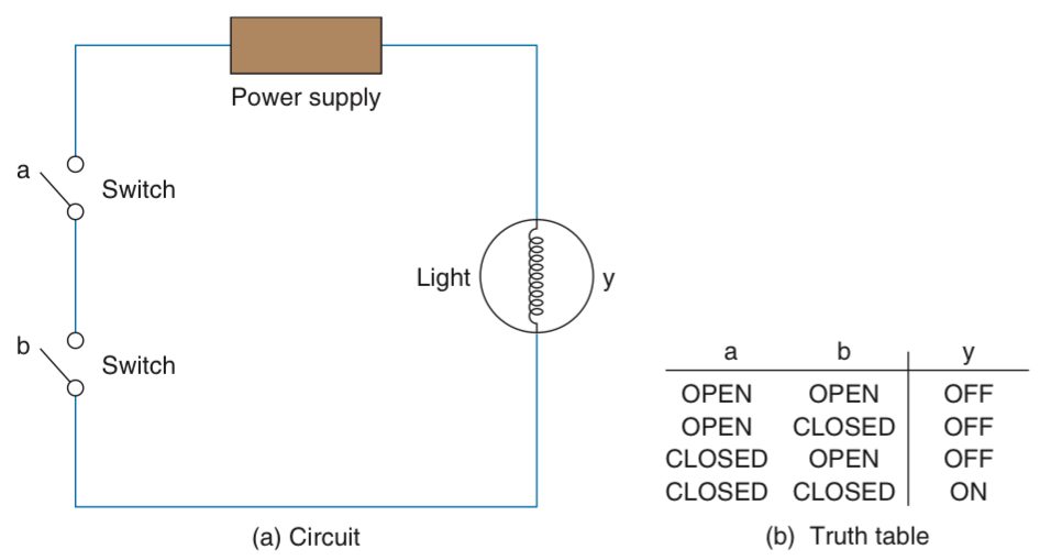
These circuits are making simple logical decisions, two switches offer four combinations of OPEN and OFF, but only certain combinations cause the light to be turned on.
- When the two switches are in series, both of them have to be closed to switch the light on, creating an AND function
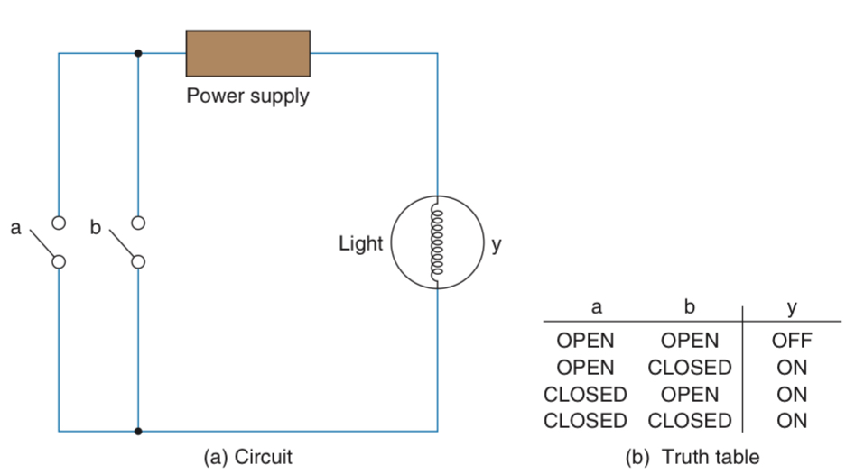
- When the two switches are in parallel, only one of them needs to be on to turn the light on, creating an OR function.
BUF vs NOT
BUF:
- the output of the BUF function has the same value as the input to the function; if the input is FALSE the output is FALSE, and if the input is TRUE the output is TRUE.
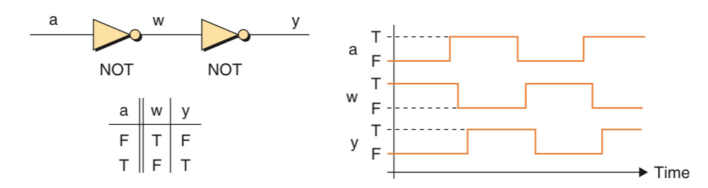
- Two NOT functions connected in series create the physical equivalent of a NOT function. The first NOT gate inverts the value and the second inverts it back against, Thus the two negations cancel each other out.
NOT:
- NOT symbol indicates an inverting function, if the input is FALSE the output is TRUE, and if the input is TRUE the output is FALSE.
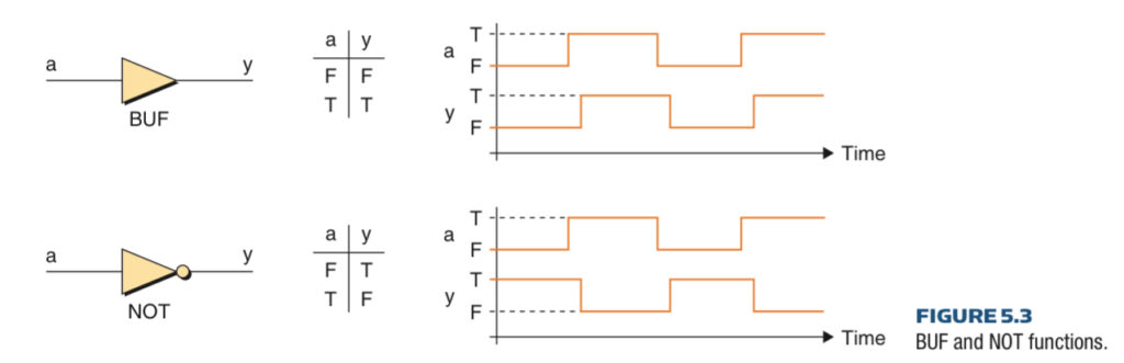
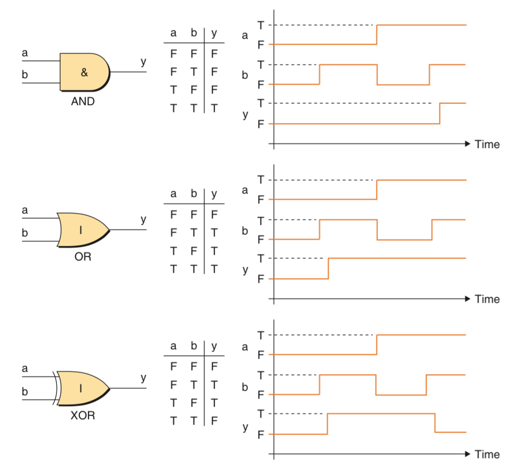
The waveforms show delays between transitions on the inputs and corresponding responses at the outputs. The actual values of these delays depend on the technology used to implement the functions.
AND & OR & XOR Functions
- AND: The output is only TRUE if both inputs are TRUE
- Inclusive-OR: The output is TRUE if either input is TRUE
- Exclusive-OR (XOR): OR function where the TRUE output cases exclude the case when both inputs are TRUE.
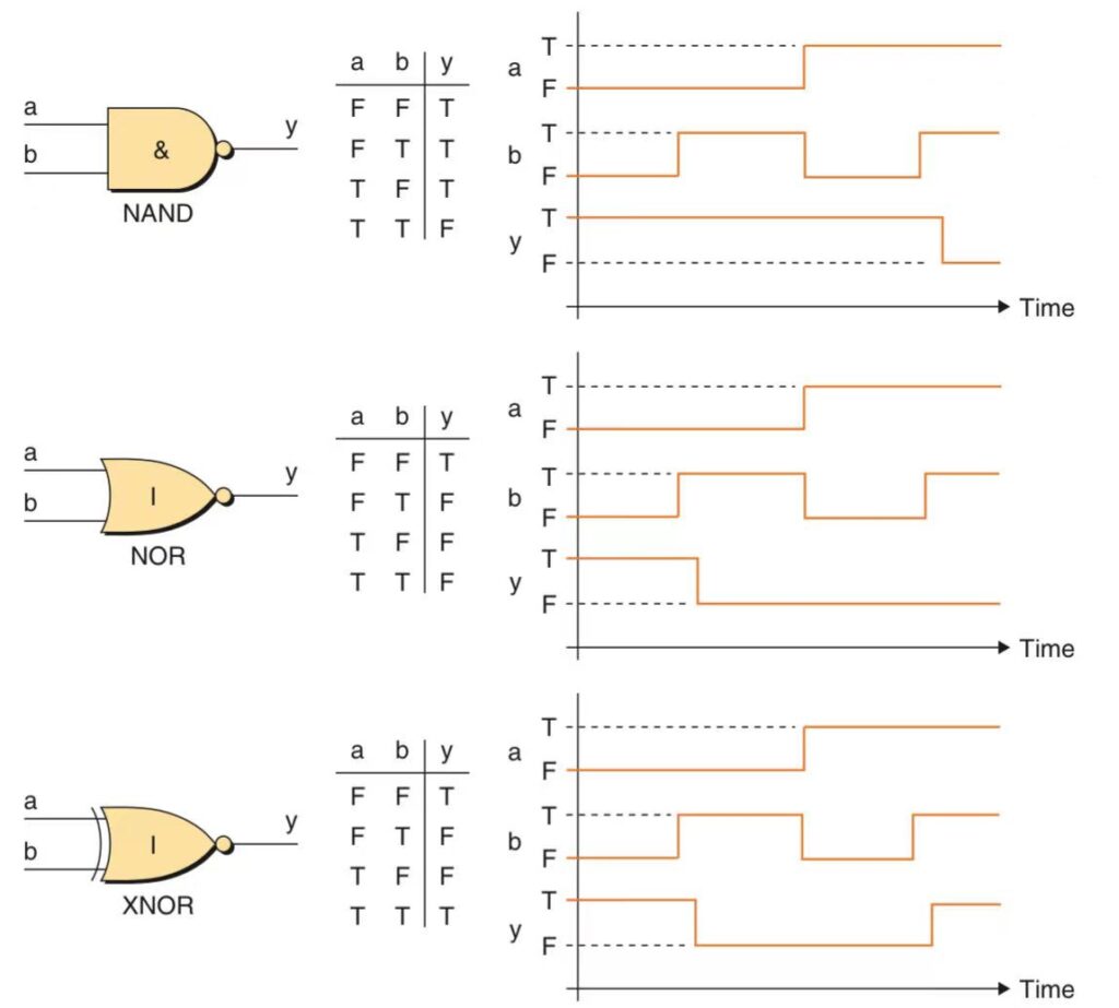
NAND & NOR & XNOR Functions
The truth table of NAND, NOR and XNOR is the opposite of AND, OR and XOR respectively
- NAND: the combination of NOT and AND logic function
- NOR: the combination of NOT and OR logic function
- XNOR: the combination of NOT and XOR logic function
Logic Functions / Gates
- There are only eight simple functions, they are BUF, NOT, AND, NAND, OR, NOR, XOR, and XNOR, these are known as primitive gates.
- The term logic function implies an abstract mathematical relationship while the logic gate implies an underlying physical implementation.
- It is possible to construct all of the above functions using one or more NAND gates (or one or more NOR gates).
In a complete design, the logic symbols are converted into appropriate equivalents such as switches, transistors or pneumatic valves. Similarly, the FALSE and TRUE logic values are mapped into appropriate equivalents such as switch positions, voltage levels, or air pressure.
BeBOP Chapter 5 Key Note: Primitive Logic Functions