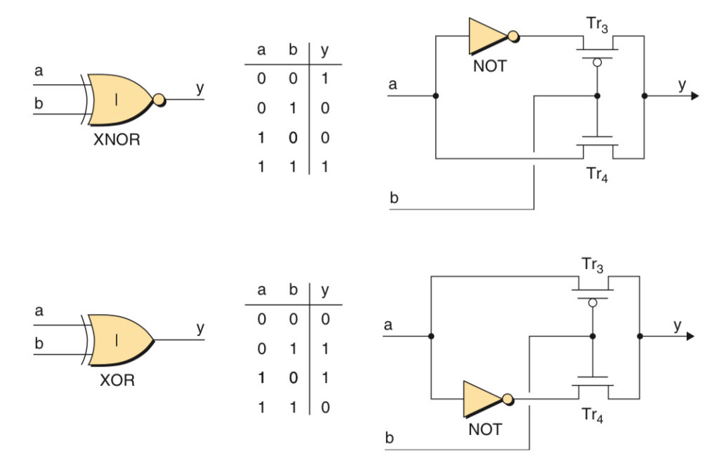
XNOR and XOR gates are primitive logic gates. In XNOR, when two inputs are the same, the output is logic 1 and when the two inputs are different, the output is 0. This gate can be built using pass-logic transistors meaning that one of the inputs is connected to the source of the transistors rather than the gate.
However, when I try to use MOSFETs to build an XNOR gate, the output of the circuit is not the same as what I expected.
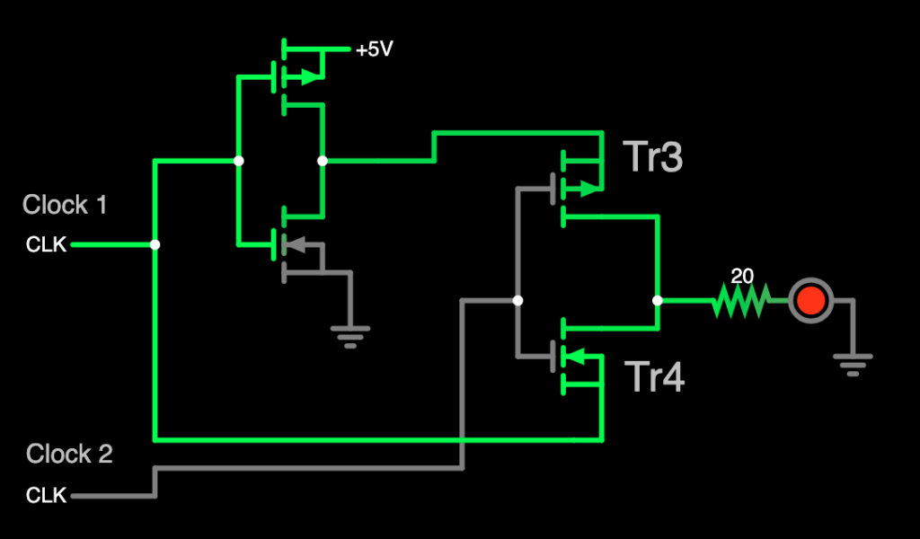
The Tr3 and Tr4 MOSFETs should work as a switch when the clock 2 signal is 0, Tr3 should be on and Tr4 should be off, and vice versa. But as shown in the picture, the simulation result shows that the Tr3 and Tr4 turned green, meaning that currents pass through the p-MOSFET and n-MOSFET. It is strange why the current is passing through n-MOSFET Tr4 even though the input from clock 2 is 0.
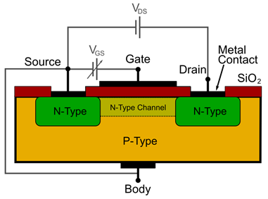
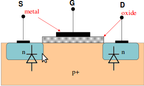
I searched on the internet, I found that actually there are 4 terminals in the MOSFETs which are source, gate, drain and body. In N MOSFET, its body must always be connected to the ground, and in P MOSFET, its body must always be connected to the power. In the circuit above, Tr3 and Tr4 are 3-terminal MOSFETs, their bodies are connected to their source internally. As the source gets input a clock signal which toggles between 0 and 1, so the body will also toggle between 0 and 1. It will trigger a parasitic diodes to turn on from the body to drain in N MOSFET and from drain to the body in P MOSFET. That is the reason why there is a current in the MOSFETs of the above circuit.
To correct this problem, I should replace the 3-terminal N and P MOSFET with the 4-terminal N and P MOSFET and connect the body of the N MOSFET to the ground and the body of the P MOSFET to the power.
Another way of implementing the XNOR or XOR gate is not using pass transistor logic.