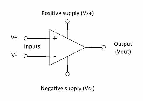
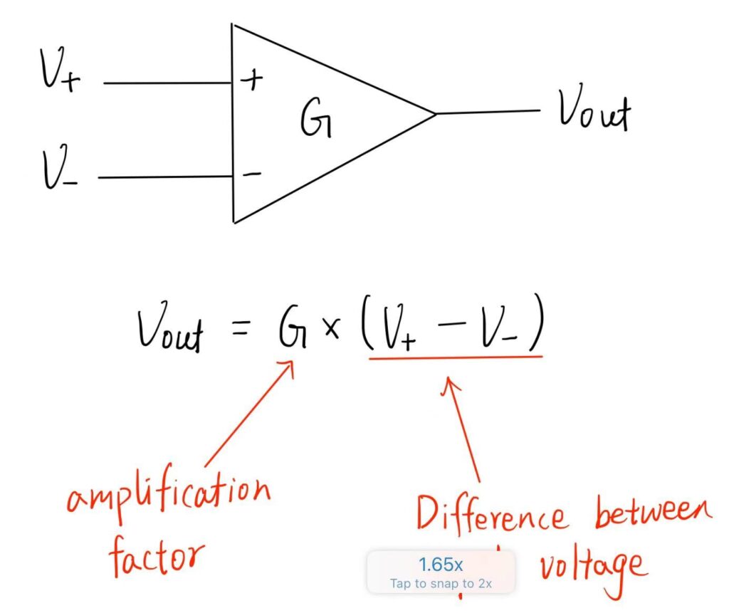
An amplifier is a device that increases the strength of the input signal. An operational amplifier also known as Op Amp amplify the voltage. It is a three-terminal electronic device, having two input terminals, a inverting terminal marked by the “-” sign and a non-inverting terminal marked by the “+” sign. The third terminal is the output terminal. The gain “G” of the op-amp is the magnification factor = voltage of output signal divided by the voltage of input signal.
The gain, “G”, of the Op-Amp is normally between 80 – 100 dB where 1 dB = 20 * lg G. For a Op-Amp, 80 dB is an amplification of 10000 times, whereas 100 dB is an amplification of 100000 times.
Open Loop Configuration
In this configuration, the Op-Amp does not have any feedback. The output voltage will be amplified to be G times the potential difference between the input terminals, but will not exceed the potential difference between the positive supple and negative supply.
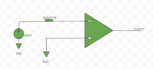
Inverting Mode:
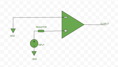
Non-inverting Mode: Input signal is connected to the non-inverting terminal “+”.
The difference between a inverting and non-inverting mode is that an inverting amplifier introduces a phase shift of 180° between the input and output signals, whereas a non-inverting amplifier has 0° phase shift (no phase shift) between input and output signals.
Closed Loop Configuration
In this configuration of the op-amp, negative feedback is used to control the amplification factor of the amplifier. A portion of the output voltage is applied back to the input. This feedback greatly reduces the gain of the op-amp as compared to open-loop gain. Thus, it is a kind of controlled way of amplification.
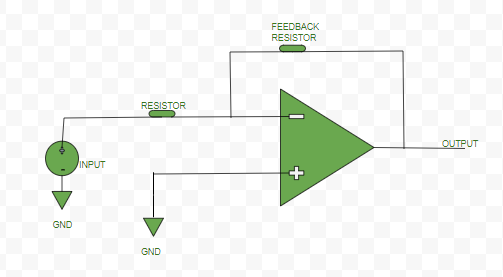
Inverting Mode:
Non-inverting Mode:
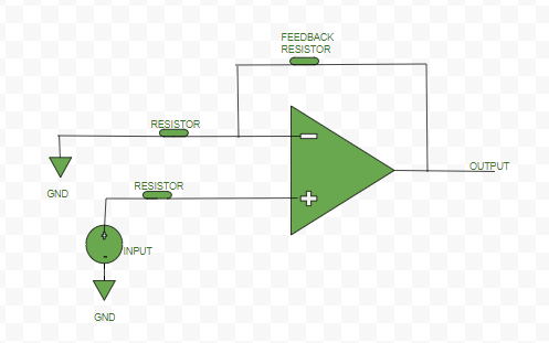
Negative Feedback Definition: Negative feedback in an op amp is defined as connecting the output to the inverting input through a resistor to control the gain.
Differential Amplifier
Operational Amplifier is a kind of differential amplifier. Differential amplifier is a type of electronic amplifier that amplifies the difference between two input voltages.
Characteristic of Ideal Op-Amp
- Open loop gain is infinite
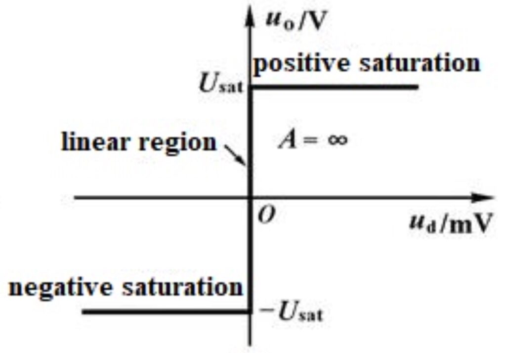
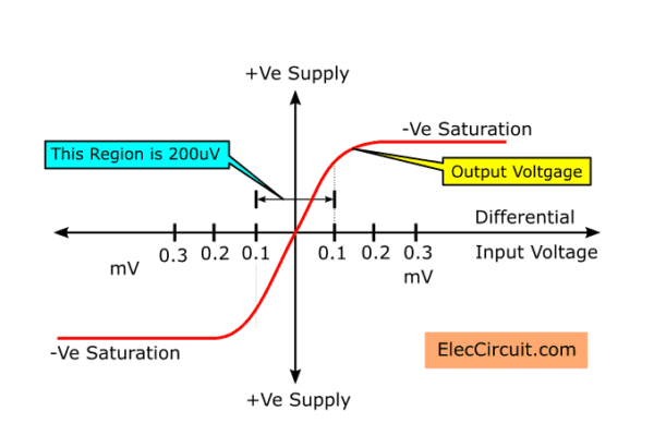
Op-Amps can have a linear response or a non-linear response depending on the difference between the input voltage. A linear response means that the output signal is directly proportional to the difference between the input signal. The Op-Amp only has a linear response when the difference between the input signals are small.
In the case of a ideal Op-Amp, the open loop gain is infinite, it is shown in the vertical part of the graph as its gradient is infinity. The difference between the input voltage must be 0 to work in this region for an ideal Op-Amp.
The following explains why the open loop gain of the Op-Amp is infinite.cc
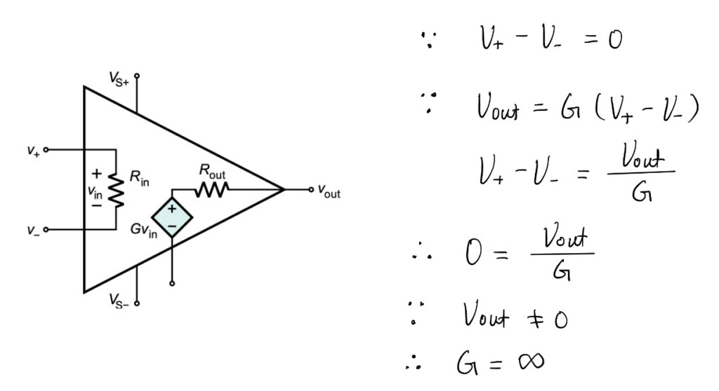
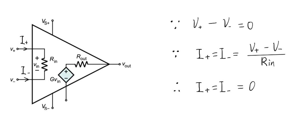
2. The input impedance is infinite
Since in an ideal Op-Amp, the difference between the inverting and non-inverting voltage input is 0, there is also no current flowing into it. Therefore, the input impedance is infinite for both input.
Virtual Short Circuit
Virtual short circuit is a theoretical situation that arises from one of the fundamental characteristics of an ideal op amp which is the infinite open-loop gain.
In reality, when the inverting and non-inverting inputs of a operational amplifier have almost the same voltage, the open loop gain for the Op-Amp is not infinite, it is some fixed value. It is shown in the graph below, as there is a curve with a finite gradient value. However, the difference between the input voltage would still have to be small in order for it to have a linear response.
To simplify the calculation process, we can usually assume that the potential difference between the inverting and non-inverting input is approximately 0.
Virtual Open Circuit
The input impedance of an ideal op amp is infinite, meaning that, if a voltage is applied to the input end of the op amp, the current flowing into and out of the input terminal of the op amp is 0, which is equivalent to a open circuit.
However, in reality, the current flowing into the Op-Amp is not 0, but a very small value. To simplify the calculation, we can approximate the current flowing into it to be 0.
Non-inverting Amplifier Analysis
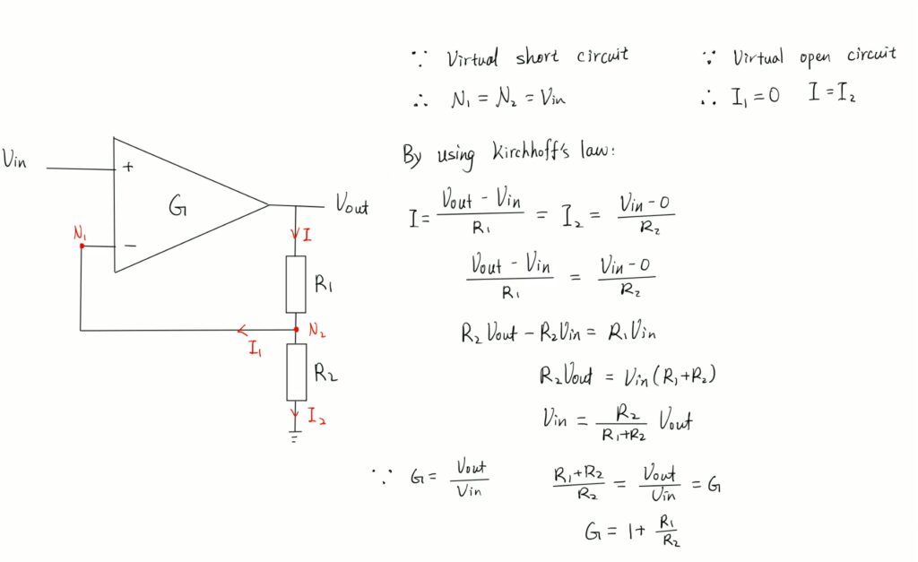
In this amplifier circuit, the input signal is connected to the non-inverting terminal of the operational amplifier. Looking at the point N1, it is connected to the inverting terminal of the operational amplifier. Due to virtual short circuit, we can assume that this point has the same voltage as the the other input which is Vin. At the output terminal, current flowing out from the Op-Amp will flow to the two resistors. Since the node N2 is connected back to the inverting terminal for feedback, it also have a voltage of Vin. Due to the virtual open circuit, the current flowing into the Op-Amp is negligable and we can assume that there is no current flowing into it. This means that the resistors in series act as a potential divider, we can use Kirchhoff’s law, find an equation to express the current through each resistor and equate them together. In this way, we can find the relationship between the input voltage and the output voltage which is the gain, to better control the magnifying factor.
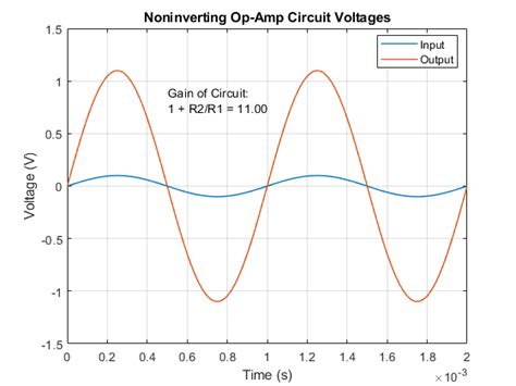
The graph for the non-inverting amplifier is shown above, the input and output wave have the same phase but the output signal has a greater amplitude.
Inverting Amplifier Analysis
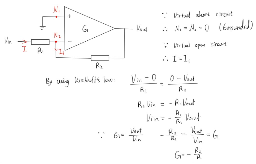
In this amplifier circuit, the input signal is connected to the inverting terminal of the operational amplifier. To analyze this circuit, we need to first determine voltage at important nodes N1 and N2. At node N1, since it is connected to the ground, it has a voltage of 0. Due to the virtual short circuit, node N2 also has a voltage of 0. If we look at the current flowing through the circuit, we would find that current I is equal to current I1 because of virtual open circuit. So, now the circuit is simplified to a potential divider as well. We can obtain the relationship between the input and output voltage by equating the current through the two resistors using the Kirchhoff’s law. Finally, we found out that the gain is related to the value of the two resistors and it is a negative value. It indicates an inversion of the output signal with respect to the input. It is 180° out of phase.
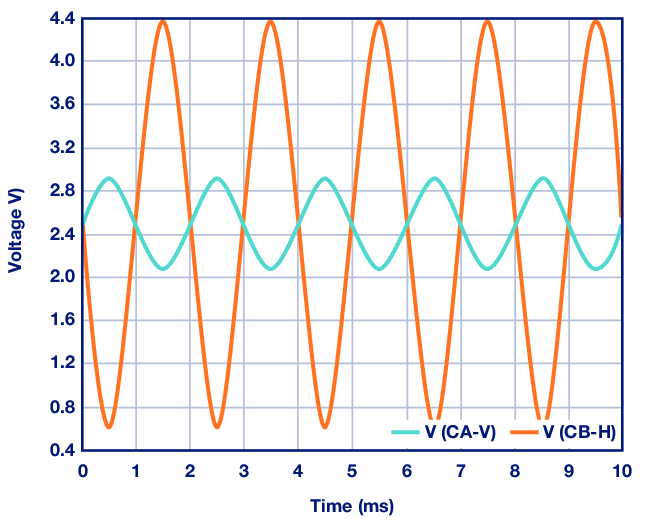
The graph above shows the relationship between the input and output signal, where the blue line represents the input signal and the orange line represents the amplified output signal.