An voltage subtractor circuit is a circuit that produces an output voltage proportional to the voltage difference of two input signals applied to the inputs of the inverting and non-inverting terminals of an operational amplifier.
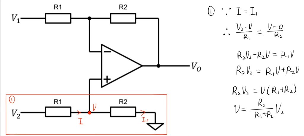
We can first analyse the part of the circuit connected to the non-inverting input. It act as a potential divider, since no current will flow to the operational amplifier, so current that flow through R1 will also flow through R2. If we set the voltage between the lower R1 and R2 to be V, we can find V in terms of V2 by equating the expression for current.
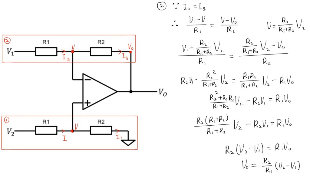
Now, looking at the upper part of the circuit connected to the inverting input, the potential difference at the point between the two resistor R1 and R2 is also V because of virtual short circuit. Similarly, since no current will flow into the Op-Amp, the current flowing through R1 will also flow throught R2, so we can write another equation. The potential difference across R1 divided by the resistance R1 is equal to the potential difference across R2 divided by the resistance R2. After solving the two equations, we can find out an expression of Vout in terms of V1 and V2. The relationship is that the output voltage is directly proportional to the difference of the input voltage.
If all the resistors are all of the same ohmic value, that is: R1 = R2 then the circuit will become a Unity Gain Differential Amplifier and the voltage gain of the amplifier will be exactly one or unity. Then the output expression would simply be Vout = V2 – V1. Also note that if input V1 is higher than input V2 the output voltage sum will be negative, and if V2 is higher than V1, the output voltage sum will be positive.