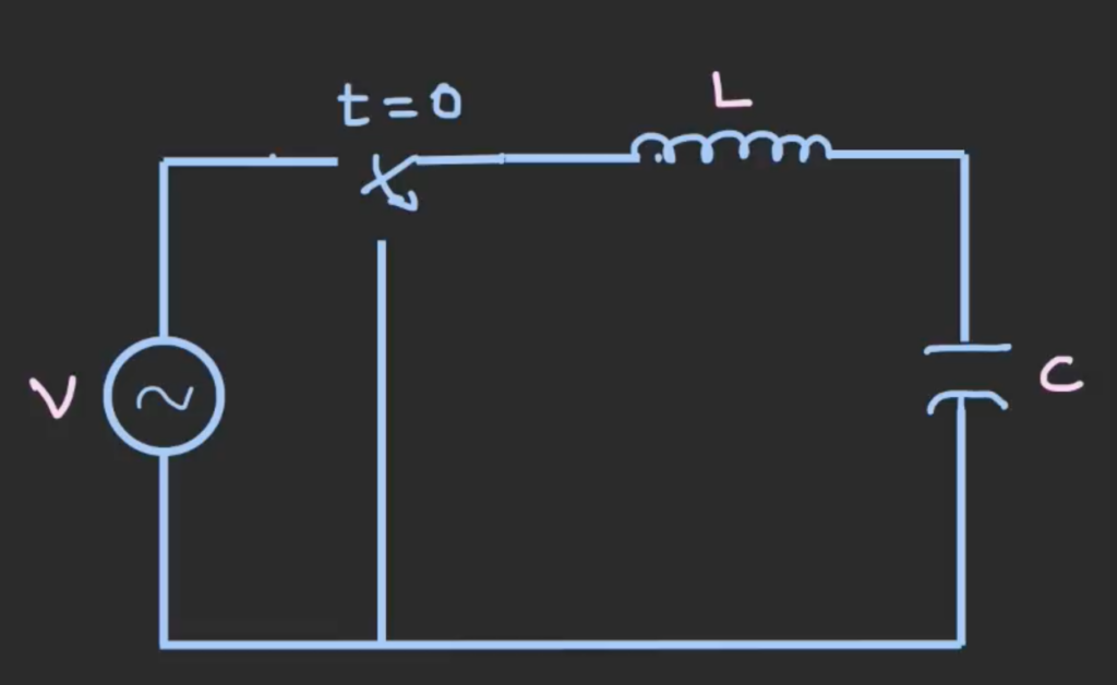
LC Oscillating Circuit
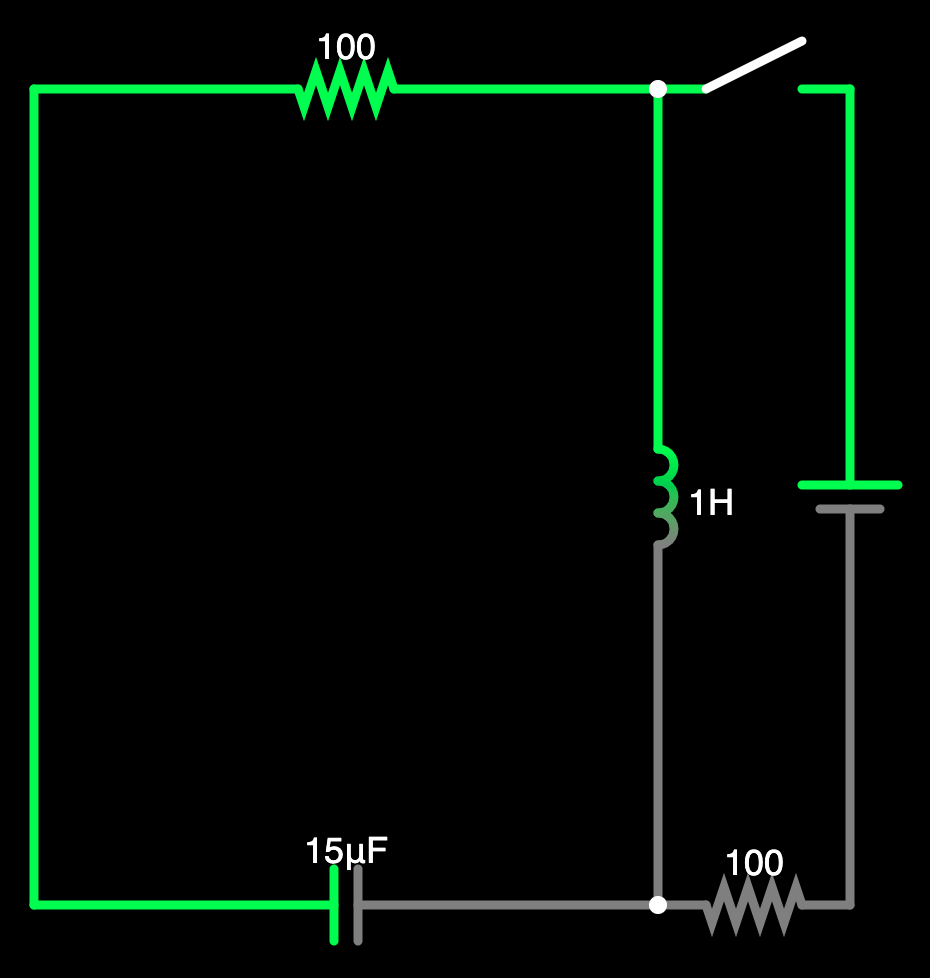
In the following AC circuit, after applying some voltage source, at time = 0 we remove this source and replace it with a short circuit. Both inductor and capacitor have to ability to story energy, inductors store energy in the form of magnetic field while the capacitor stores energy in the form of electric field. The inductor will supply a current to charge the capacitor and the capacitor will act as the energy source to supply energy back to the inductor. The energy will transfer between the two component and this transfer of energy cause the oscillation in the circuit. If the circuit is ideal and has no resistance, the oscillation will go on forever, but all circuit have some resistance, energy will be dissipated on the resistance, so the oscillation will eventually end.
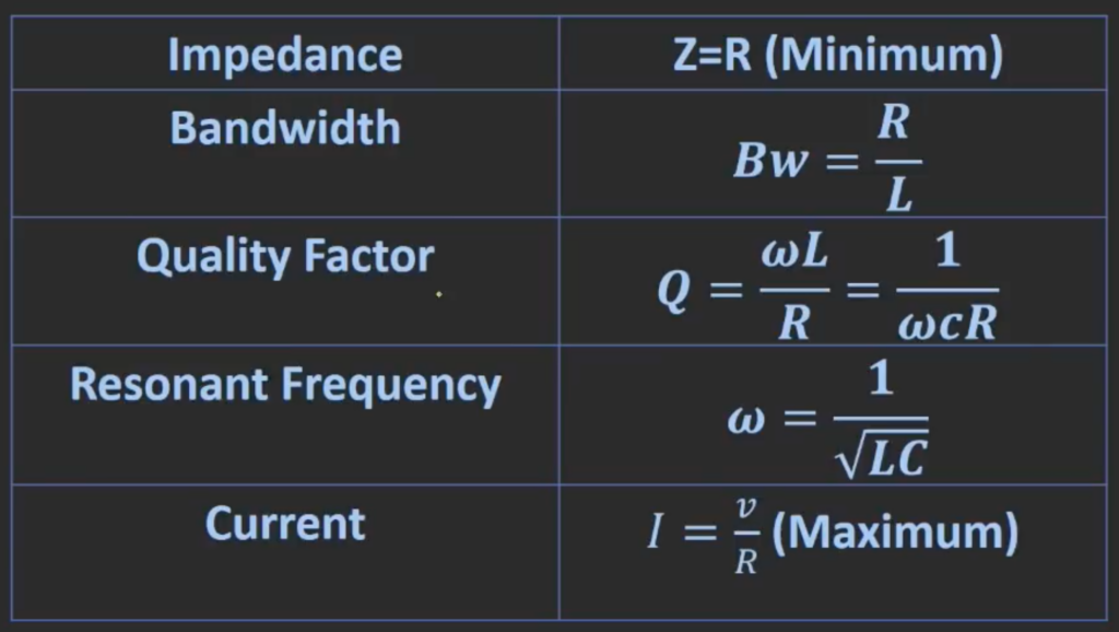
Resonant Frequency in RLC Circuit
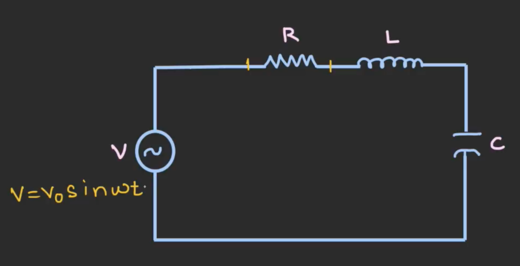
When we apply an alternating voltage of a certain frequency to the RLC circuit, there will be current flowing in the circuit. If we change this frequency of the input voltage, at a particular frequency, there will be a maximum current flowing in the circuit.
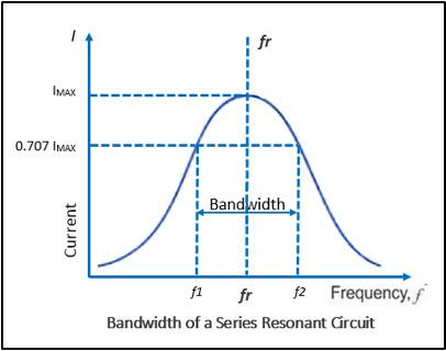
The graph for this phenomenon will look like the following, at lower or higher frequency, there will not be any current flowing through the circuit. When the frequency of the input voltage is the resonant frequency, there will be maximum current flowing through the circuit.
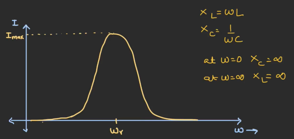
We know that the capacitive reactance XC is given by 1/jωC, and the inductive reactance XL is given by jωL. When the frequency if 0, the capacitive reactance is infinity, so it act as an open circuit therefore no current will flow. Similarly when the frequency is infinity, the inductive reactance would be infinity, it will also act as an open circuit and no current will flow. When the capacitive reactance is equal to the inductive reactance, the impedance of the circuit is purely resistive, it would give the maximum current.
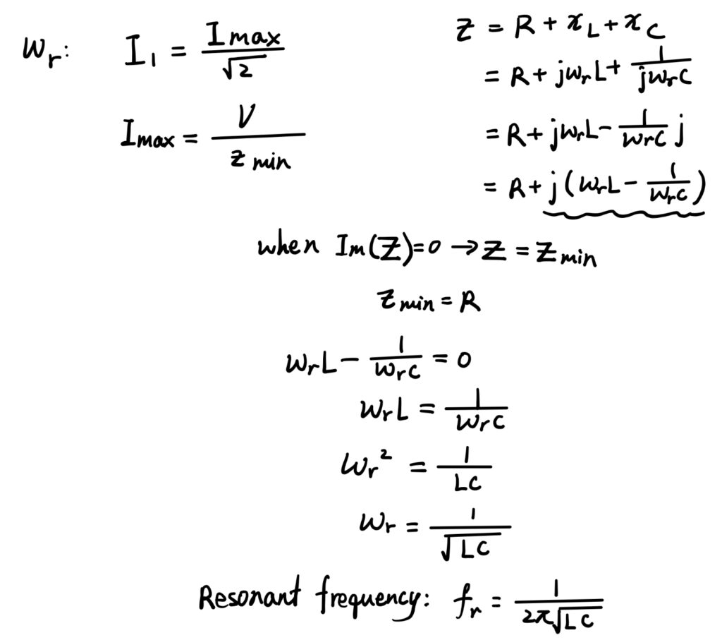
Derivation of the Formula of Resonant Frequency:
To find the resonant frequency, we need to find at which frequency we can obtain the maximum amount of current. To find maximum current, we need to find the minimum impedance of the circuit since I = V/R. We can get the minimum impedance when the imaginary part of the circuit is equal to 0, therefore, if we equate the imaginary part to zero, we can find that the resonant frequency for an RLC circuit is equal to 1/[2π√(LC)]
Role of Resistance
Resistors will apply damping to the circuit which has two major effect:
- It reduces the current magnification
- It increases the bandwidth of the circuit.
In an oscillating circuit, the resistor provides damping, which is the reduction of the amplitude of oscillations over time. Without a resistor, the oscillation would continue indefinitely because the inductor and capacitor would exchange energy with no loss. With the presence of some resistance, energy will be dissipated across it. The higher the resistance, the more damping effect is has, causing the amplitude of the current oscillations to decrease more rapidly.
Resistor = 100 Ohm:
Resistor = 50 Ohm:
Bandwidth
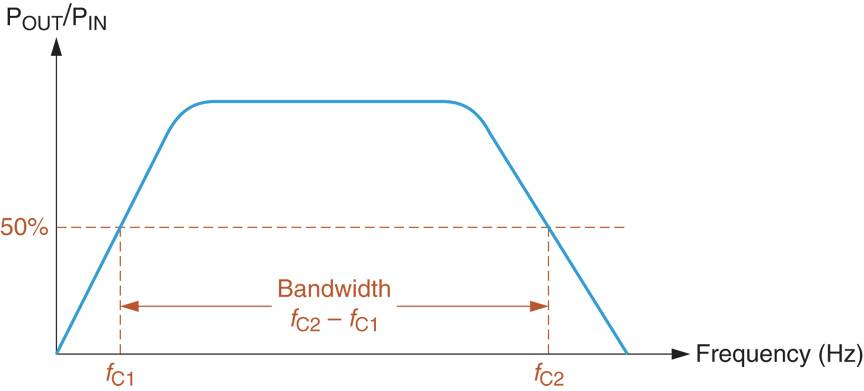
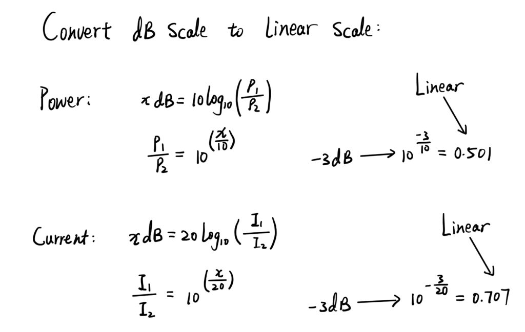
The bandwidth of a circuit is typically defined as the range of frequencies over which the circuit can effectively operate. It is the difference between the -3dB frequencies in the circuit, which is the difference between the half power frequencies.
Convert dB scale to Linear Scale:
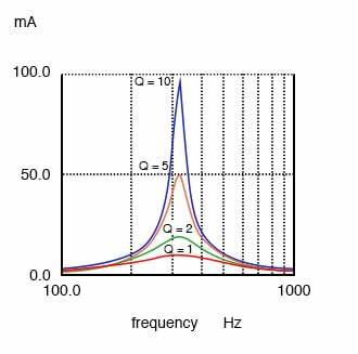
Increasing the resistance of the resistor can increase the bandwidth of the circuit because the bandwidth can be thought of as the range of frequency around the resonant frequency where the circuit’s response is strong. A higher resistance broadens this width because it causes the oscillations to decay more quickly, allowing the circuit to be more responsive to a wider range of frequencies. We want an oscillating signal to decay to ensure that once the signal has passed, it does not interfere with subsequent signals. More damping (higher resistance) results in a broader peak and a wider bandwidth. Whereas less damping (lower resistance) results in a sharper peak and a narrower bandwidth.
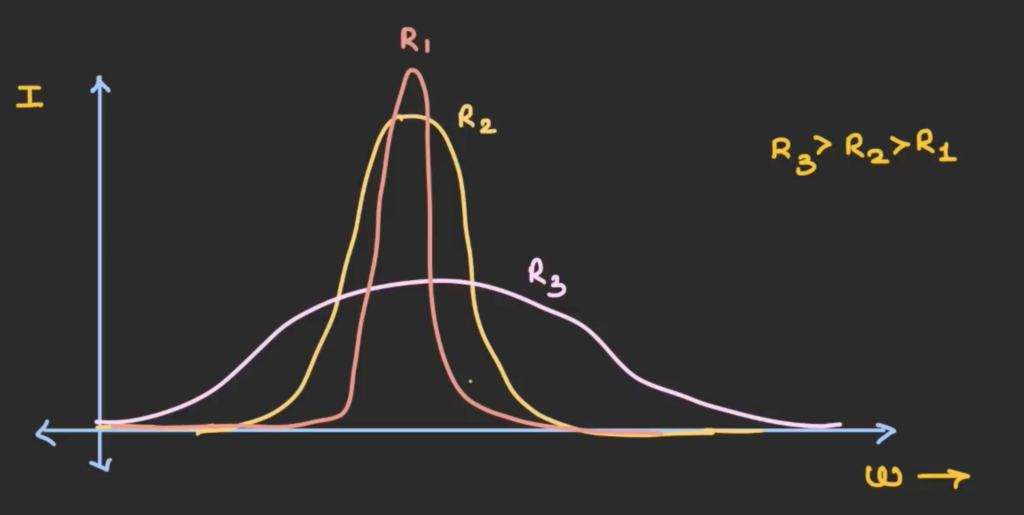
As we can see from the curve, the curve for R1 has the highest peak and the curve for R3 has the lowest peak. Higher resistance reduces the current magnification because current is voltage divided by resistance, at resonant frequency, the inductive and capacitive reactances cancel each other out, and the current of resistance only depend on resistance. So, as resistance increase, the current decrease.
A higher curve indicates that the peak current is maximum and only voltage source of a smaller range of frequency can be selected. For good selectivity, the resistance of the circuit should be as small as possible.
Derivation of the Equation for Bandwidth:
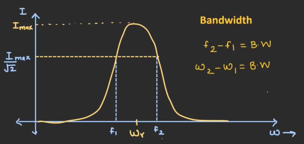
The graph above shows an amplitude frequency curve where the size of current indicates the signals amplitude. The band width of the curve is the difference between the -3dB frequency.
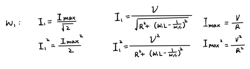
We can find the relationship between the current at the limiting frequencies and the maximum current. The “3dB” for current is 1/√2 on the linear scale which is about 0.707 times the maximum current. Next we need to find an expression for both maximum current and current at limiting frequency.
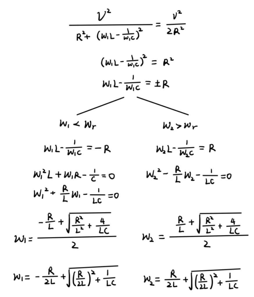
Next wee need to equate the two expressions and simplify the equation. We obtain two equations, one will solve for the maximum frequency and the other will solve to get the minimum frequency. When we solve the quadratic equation, we would obtain two solution but one of them is negative, since frequency cannot be a negative value we need to reject those negative solutions. Finally, we will find the expression for the two limiting frequencies in terms of R, L and C.
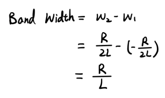
Lastly, we need to subtract ω1 from ω2 to get the difference of the -3dB frequencies. The expression for the bandwidth of an RLC circuit is given by R/L.
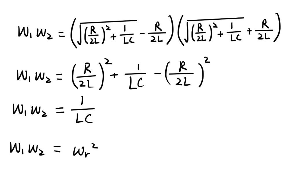
Another interesting characteristic is that if we multiply the upper and lower limiting frequencies together, it is equal to the square of the resonant frequency.
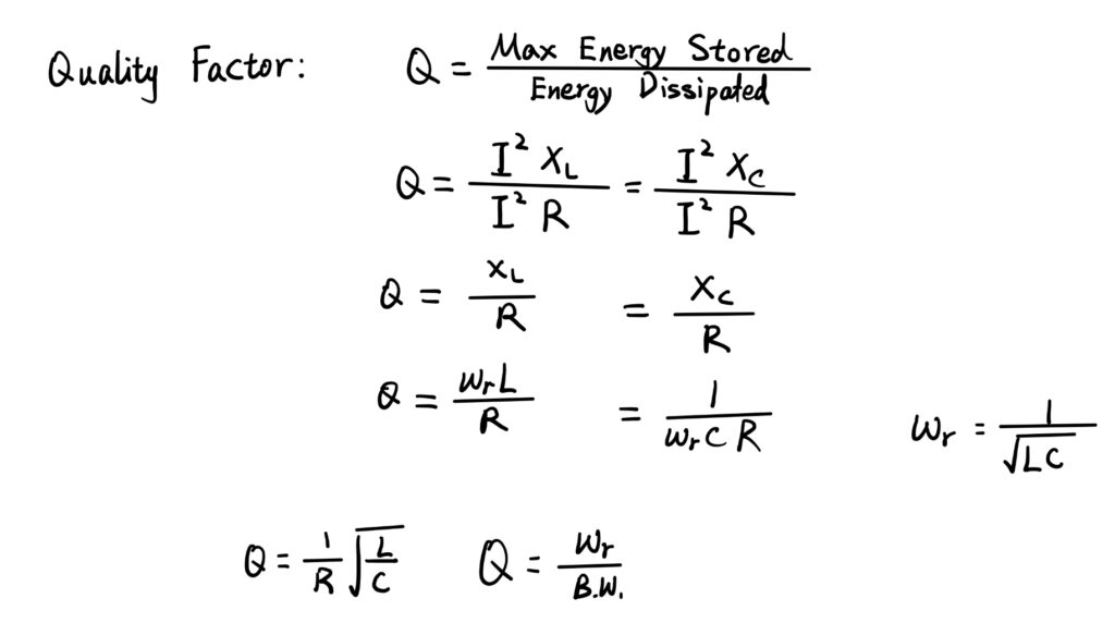
Quality Factor
The quality factor is defined as the ratio of the energy stored in the system to the energy dissipated. A high quality factor indicates a narrow and sharp resonance peak, it means that the system is highly selective and has a strong response at its resonant frequency.
Derivation of Expression for Quality Factor:
Maximum energy stored can be calculated using square of maximum current multiply by the reactance of inductor or capacitor. Energy dissipated is the amount of energy dissipated on resistors. After simplifying the equation, we can find that quality factor is equal to the resonant frequency divided by bandwidth.
Summary: