An electronic filter is a circuit which passes some frequency components in the circuit and reject or attenuate all other frequency component.
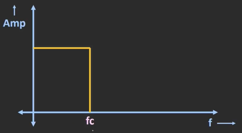
This curve shows an ideal low pass filter that passes the low frequency signal starting from 0 Hz to the cut off frequency. Any frequency component beyond the cut off frequency will be rejected.
There are two main category of low pass filter, they are the active low pass filter and the passive low pass filter.
Passive Low Pass Filter (Passive LPF)
A passive LPF is a circuit designed only using passive devices including resistors, capacitors and inductors. There are three type of passive LPF, they are the passive RC LPF, the passive RL LPF and the passive RLC LPF.
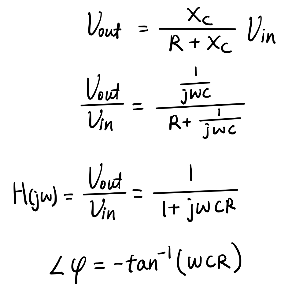
The above circuit diagram shows an first order RC low pass filter. By analysing the current flowing through the resistor and capacitor, we can establish an equation, potential difference across the resistor divided by the resistance R is equal to the potential difference across the capacitor divided by the capacitive reactance. After simplifying it, we will find the relationship between the input voltage and the output voltage.
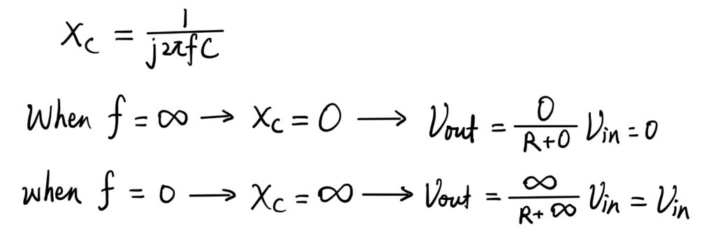
We can substitute critical values for frequency into the equation to find out whether this circuit is a high pass or low pass filter. If input frequency is infinity, the capacitive reactance is zero. It means that the capacitor can be seen as a wire, then the output voltage is directly connected to the ground, therefore it shares the same potential with the ground which is zero volts. On the other hand, when the input frequency is zero, the capacitive reactance goes to infinity. It means that the capacitor can be seen as an open circuit, and it is no longer connected to the ground. So, the output voltage will be the same as the input voltage. From this trend, we can conclude that this circuit will only allow input that have low frequency to pass.
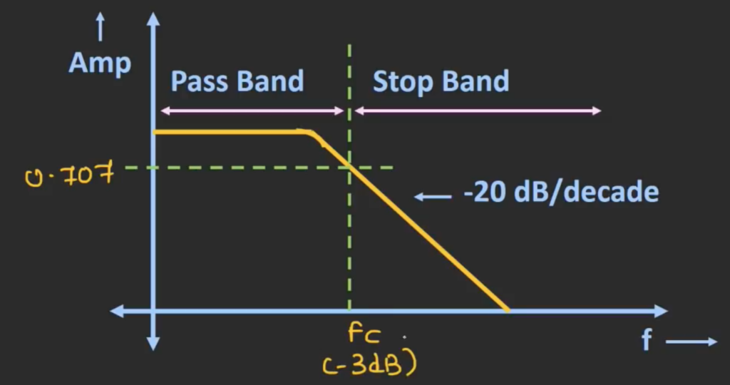
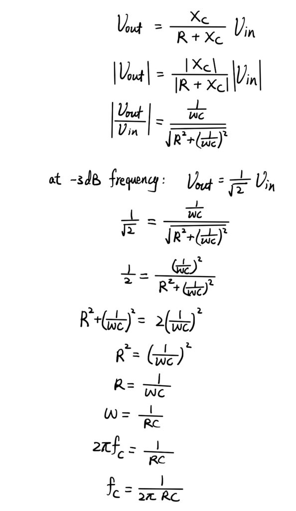
The frequency response of a actual RC low pass filter will look like the graph above. Unlike the ideal RC LPF, as long as the input frequency is above the cut-off frequency, the signal disappears immediately. At lower frequencies the actual filter provide minimum or zero attenuation and as the frequency increases, the attenuation of the input signal will also increase. The cut-off frequency is the frequency when the output is 1/√2 or 0.707 times the input, it is also known as the -3dB frequency. To find the expression for the cut-off frequency, we can utilise the relationship between the input and output voltage. Notice that we take the modulus of both side when we are simplifying the equation, this is because the capacitive reactance is a imaginary term with a 90 degrees phase different, but here we only care about the magnitude of the input and output voltage. So, by finding the modulus, we can obtain its magnitude.
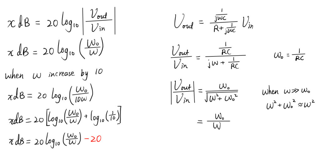
Notice from the graph that after this cut-off frequency the output will reduce at the rate of -20dB per decade. A decade is a X10 increase in frequency. This means that every time the frequency increases by a factor of ten, his output decreases by a factor of ten. The following image presents a set of equations to calculate the gain in decibels. It is calculated using the first formula. When the input frequency is a lot larger than the cut-off frequency, the ratio of the output voltage to the input voltage can be represented using the cut-off frequency over the input frequency. If we increase the input frequency by a factor of 10, the gain will decrease by a 20dB as shown by the equation.
In the case of a low pass filter, as the input frequency is increased, not only the output of the signal would reduce, but its phase will also get changed.
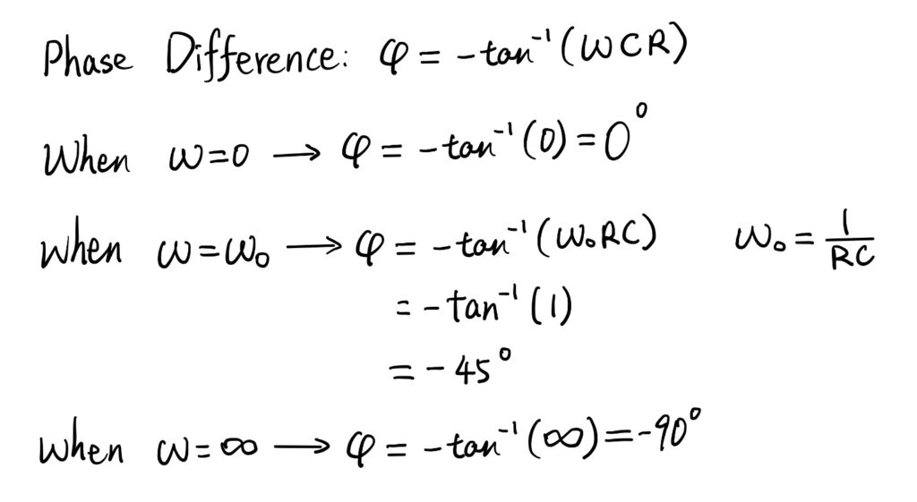
The change of phase can be given by the following equation.
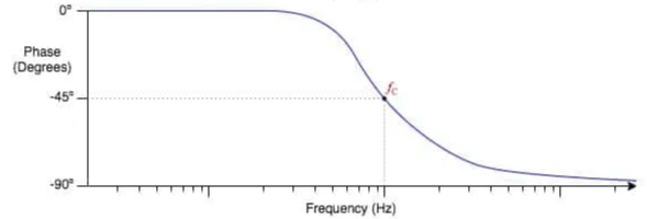
When the frequency is zero, there would be no phase shift, the input signal can directly pass over the filter. When the frequency is the cut-off frequency, the phase difference is -45 degrees and when the frequency is infinity, the phase difference is -90 degrees.
If we plot the phase difference versus frequency curve, it will look like the following.