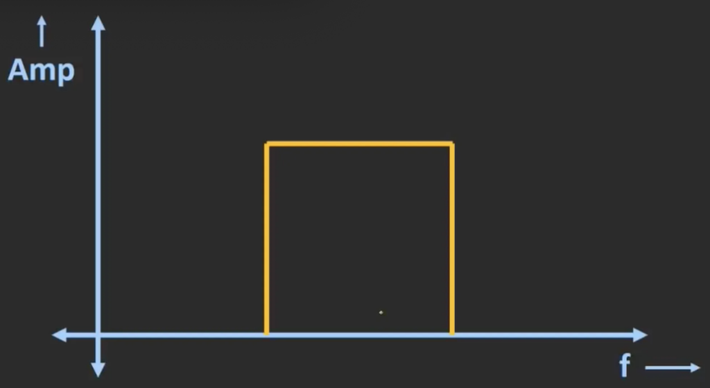
The band pass filter passes frequency components within a certain range, and rejects all the frequency component which is outside this band. The following curve shows the respond of an ideal band pass filter.
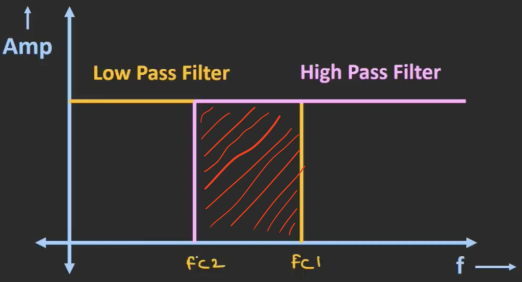
Lets say we have a low pass filter with cut-off frequency fc1, and a high pass filter with cut-off frequency fc2, if we cascade them together, we will get the overlapping region between the responses of the two filter. This overlapping region will act as a band pass filter.
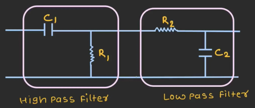
The following diagram shows the structure of a basic band pass filter by just connecting the circuit for high pass filter and circuit for low pass filter in series.
The graph below is a frequency response graph for the band-pass filter, it has a bass band between fc1 and fc2 where the signal is passed through with minimal loss. The bandwidth of the circuit is the range of frequency over which the filter allows signals to pass through with minimal attenuation. It is the frequency difference between the -3dB frequencies which are the cut-off frequencies. Similar to the RC LPF and RC HPF, in the regions beyond the cut-off frequencies, the attenuation of the signal is -20 dB / decade.
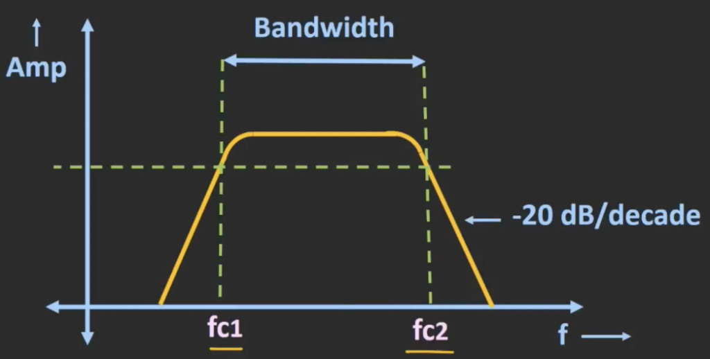
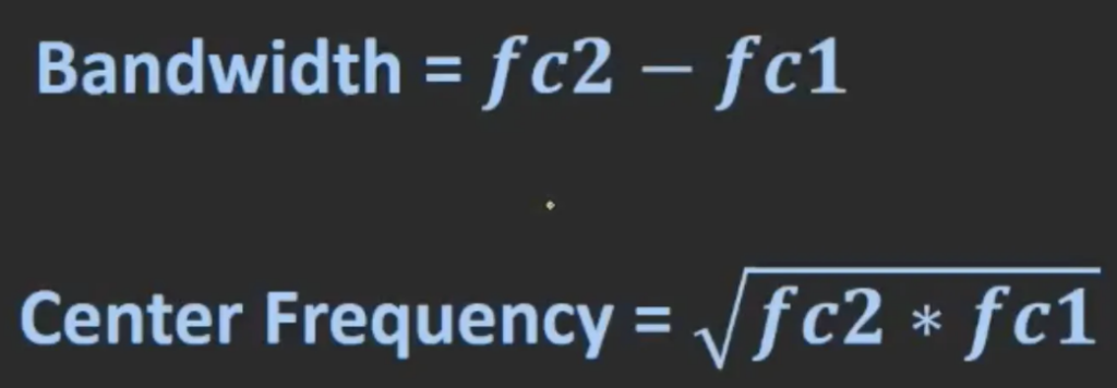
The first equation in the following image is for calculating the bandwidth which is just the difference between the two cut-off frequencies. The second equation is used for calculating the center frequency. The center frequency is also known as the geometric mean frequency, it is calculated by taking the square root of the product of the upper and lower cut-off frequencies. This value represents the midpoint of the bandwidth.
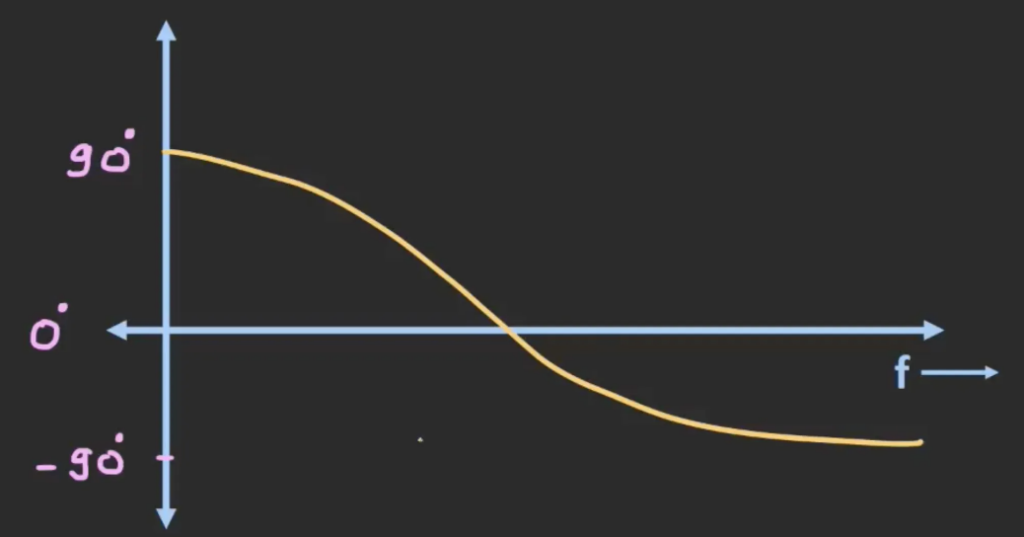
The following graph shows the phase response or the phase difference when signals of different frequencies are being inputed into the circuit. At zero frequency, the output will lead the input by 90 degrees. As the input frequency get closer towards the center frequency, the phase difference will reduce. At infinity frequency, the output will be lagging the input signal by 90 degrees.
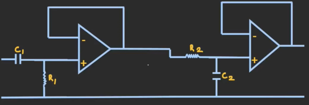
There is a potential problem in the circuit above, as the circuit is designed using only passive components, the actual value of the cut-off frequencies will be slightly different from the calculated values. The reason is that the capacitive reactance will change with frequency. This can alter the filter’s behaviour and shift the frequencies at which it starts to let signals through and stops letting signals through. To avoid that, we can isolate the two stages by using buffer. In this way, we can not only separate the two stages but also achieve gain out of this filter. The following image shows an active band pass filter.