AC To DC Conversion
Since the diode only allows current to flow in one direction, one application of it is to convert alternative current to direct current. The process of converting the AC to DC is known as rectification.
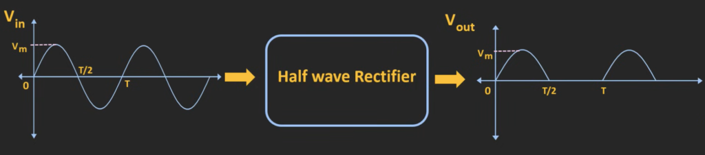
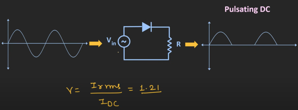
When a sine wave is applied as an input signal to the half wave rectifier, it only allows half of the sine wave and reject the other half. In this way, this rectifier converts the AC signal into pulsating DC signal.
Circuit For Half Wave Rectifier
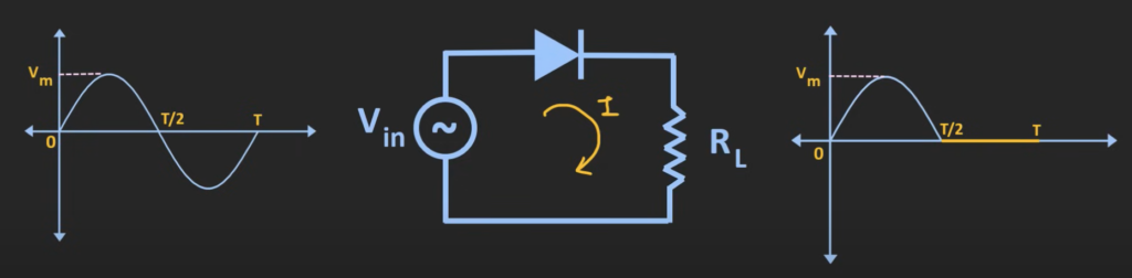
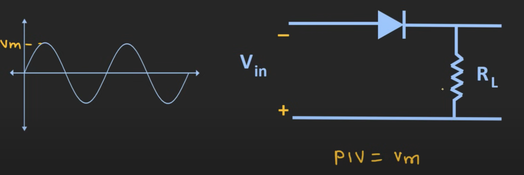
This circuit only passes the positive half cycle of the signal and completely reject the negative half.
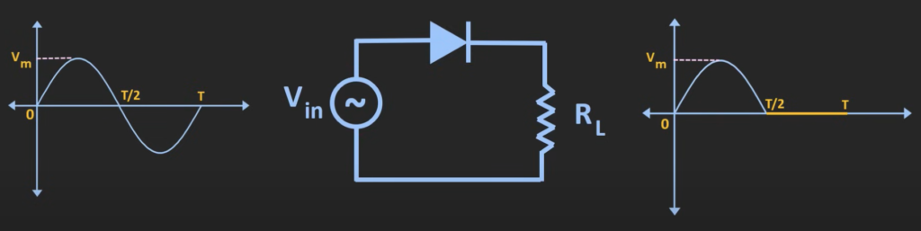
If the diode is an ideal diode, in the positive half cycle, the voltage across the diode is forward biased and thus it acts as a closed switch. On the other hand, in the negative half cycle, the voltage across the diode is reverse biased, therefore it acts as an open switch allowing no current.
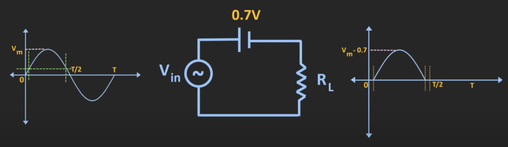
In an actual silicon diode, the diode will only become forward-biased when the applied voltage is more than the threshold voltage which is 0.7V.
Parameters for Diode
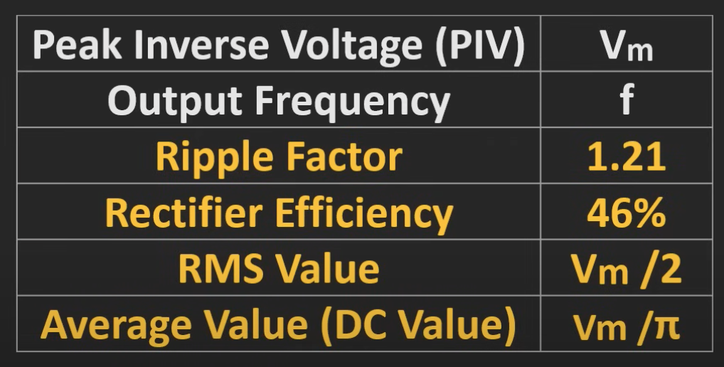
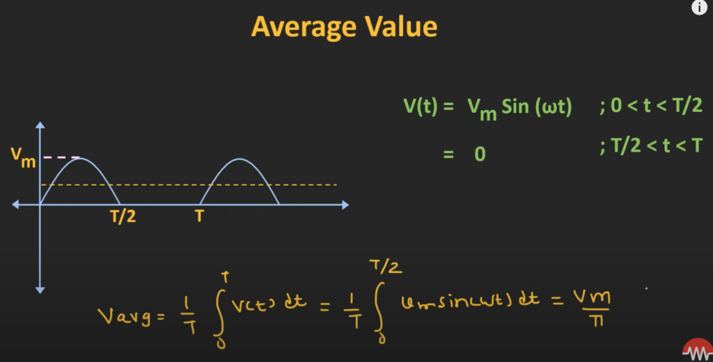
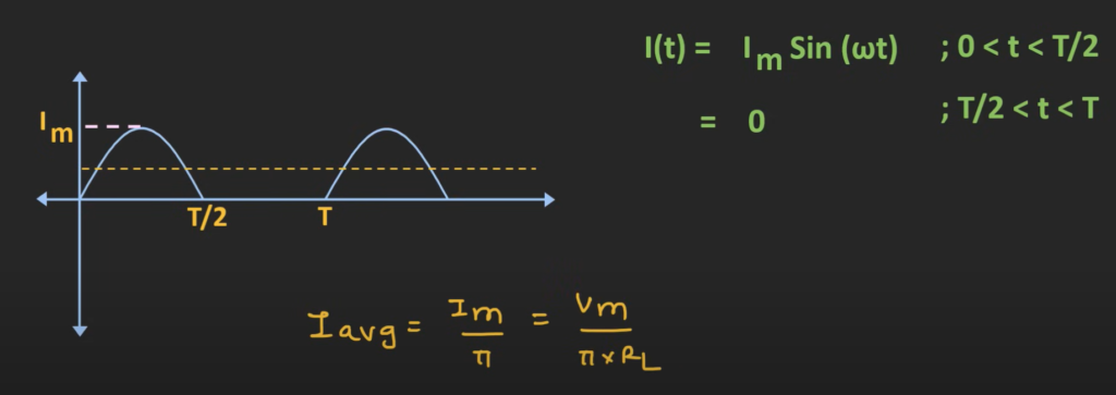
Average Value: To find the average voltage of the wave, we need to find the total area under the curve for a period and divide it by the total amount of time. The formula to calculate average voltage is Vm/π where Vm is the peak value of the voltage.
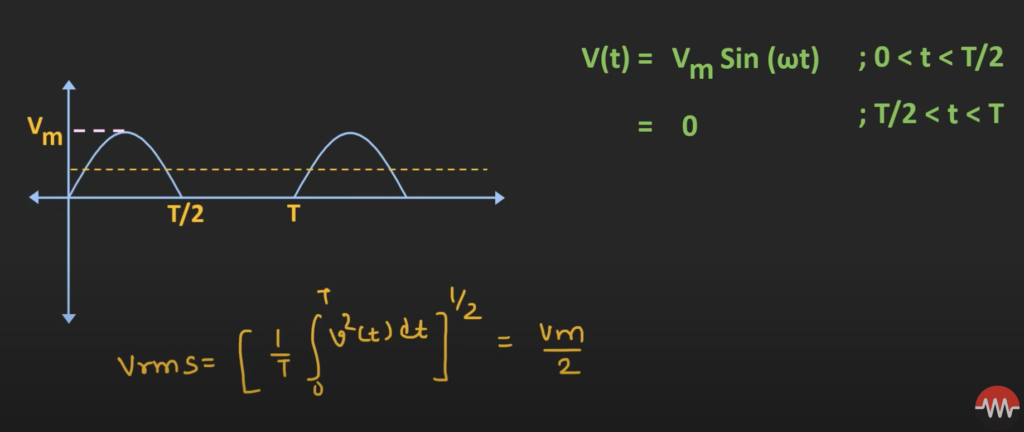
RMS (Root Mean Square) Value: it is a type of mean, It is useful when trying to measure the average “size” of numbers, where their sign is unimportant. The formula to calculate it is Vm/2 where Vm is the peak value of the voltage.
Current
Whenever the diode is conducting, a finite amount of current will also flow through the circuit. Since Vm is the peak amplitude of the wave, the peak value for the current can be given by Vm / R. (If we consider the diode to be an ideal diode)
Average Value for Current: We can use the average value for voltage to find the average value for current as their relationship is V=IR, so the formula to calculate the average current is Vm / (πR).
Peak Inverse Voltage (PIV)
Peak inverse voltage is the maximum reverse voltage applied to the diode during the operation. The PIV for a sine wave signal with a peak of Vm, the maximum inverse voltage would also be Vm. This value is important when selecting a suitable diode for the circuit, as this peak peak voltage input should be less than the PIV rating of the diode.
Ripple Factor
The ripple factor is the ratio of the RMS value of an alternating current component in the rectified output to the average value of the rectified output. The value of the ripple factor for a half wave rectifier is 1.21.
Half Wave Rectifier with Filter
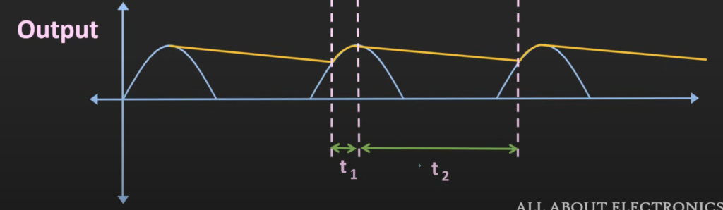
The ripple factor in the output wave form can be significantly reduced by connecting the capacitor across this load. During the positive half cycle, the voltage across the diode is forward biased, it will act as a closed switch. Through this diode, the capacitor will get charged up to the peak voltage of the input signal which is Vm. At this point, it has the same voltage at both it’s anode and cathode, the diode become reversed biased acting as an open switch. After this, the charge stored in the capacitor will get discharged through the resistor R. The yellow line on the graph represent the discharging of capacitor. The capacitor will recharge whenever the input voltage is greater than the capacitor voltage.
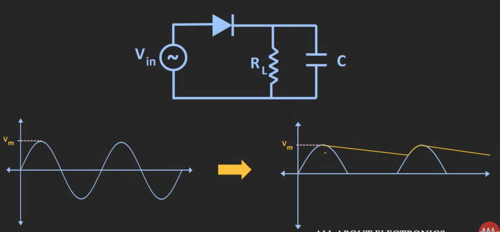
Due to charging and discharging, this is the output waveform we will get for a half wave rectifier with filter. Time t1 is the charging period of the capacitor while the time t2 is the discharging period.
Efficiency
Efficiency is a parameter that measures how efficiently the AC input power is converted into the DC output power. For the half wave rectifier, the efficiency is only 40.6 percent.

Application of Half Wave Rectifier
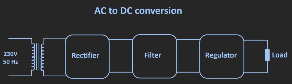
AC to DC conversion: The input voltage is steped down using the step down transformer. Then it is applied to the rectifier circuit, with an pulsating DC voltage as the output. The ripple in the output waveform is reduced using the filter circuit. Although the filter circuit can reduce the ripple, but there is still some variation of voltage in the output and that can be removed using the regulator circuit.
Important Parameters for Half Wave Rectifier