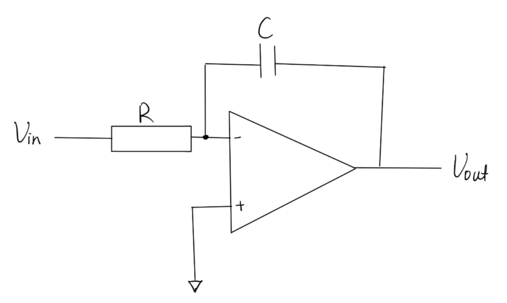
An Op-Amp Integrator is a circuit that uses a operational amplifier, a capacitor and a resistor to calculate the integral of the input signal. Its output is the cumulative effect of the input signal over time. The circuit for it is illustrated in the following photo.
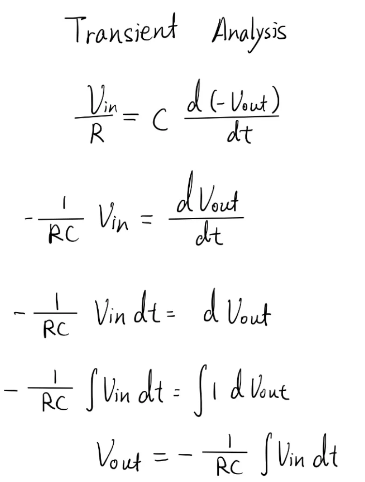
If we do a transient analysis of the circuit by equating the current across the resistor to the current across the capacitor, we would get a differential equation as the current through the capacitor is proportional to the derivative of the potential difference across it. After rearranging the equation and isolating the variable Voltage output, we can get a relationship between Vin and Vout, where the integral of input voltage to time is directly proportional to the output voltage. This relationship provide the circuit with an integration property.
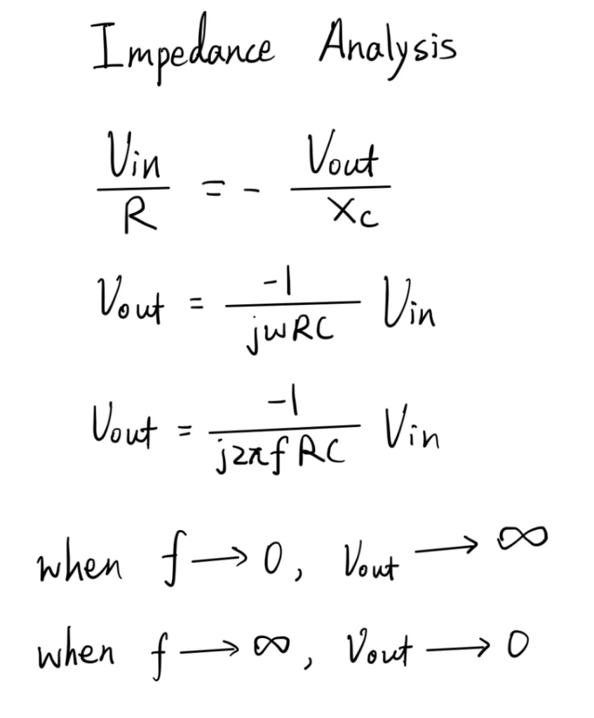
We can also do an AC analysis which analyse the circuit using only the impedance. Similarly, we again equate the current across the resistor and the capacitor, but this time we need to use the the capacitive reactance to express the current through the capacitor. After simplification, we can find a equation relating the output voltage to the input voltage. This equation shows another characteristic of this circuit, this circuit can also act as a active low pass filter. This is because when the frequency is zero, the capacitor can be seen as a open circuit, in this case, it forms a open loop configuration where the Voltage output is equal to the input voltage multiply by the gain of the operational amplifier which varies for different Op-Amps. On the other hand, when frequency is infinitely large, the capacitor can be seen as a wire that directly connect the inverting input to the output. Since the non-inverting input is connected to the ground, due too virtue short circuit, the output voltage would also be zero. This means that there is significant attenuation for high frequency signals.
This AC response may be useful when the input signal is oscillating, meaning that the error is not reaching zero but instead fluctuating above and below the target point. This oscillation of the system can cause the input of the integrator to be a signal similar to an AC signal, and thus may have these properties.