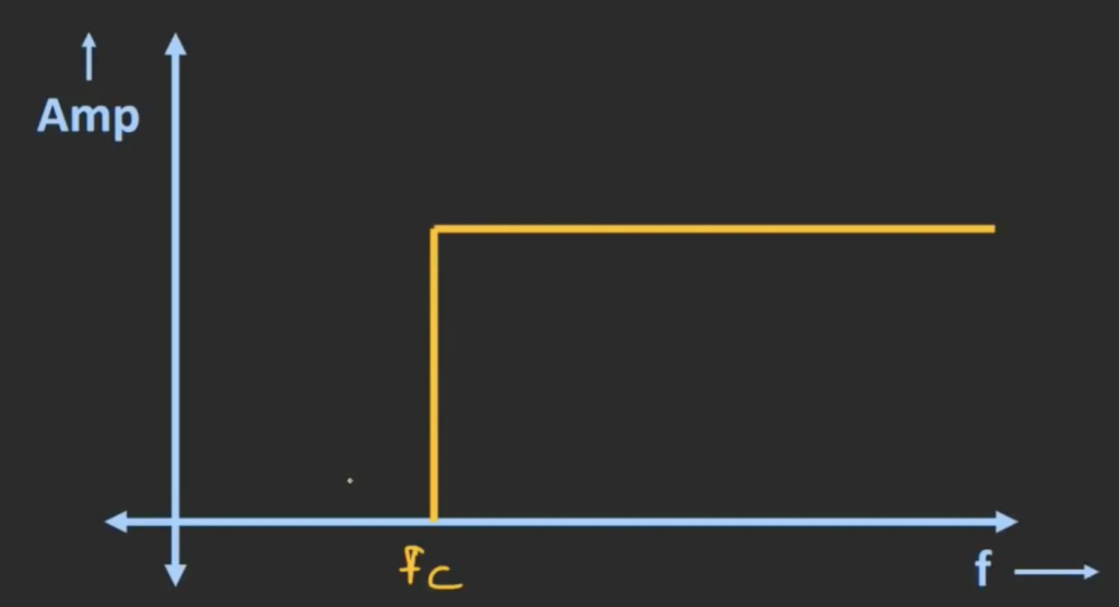
A high pass filter passes all the frequency component that has frequency above the cut off frequency and rejects all frequencies from 0 Hz to the cut off frequency. The following curve shows the respond of an ideal high pass filter.
The passive RC high pass filter circuit can be designed in two combinations like resistor and capacitor (passive RC HPF); resistor and inductor (passive RL HPF) based on the application.
Passive High Pass Filter (Passive HPF)
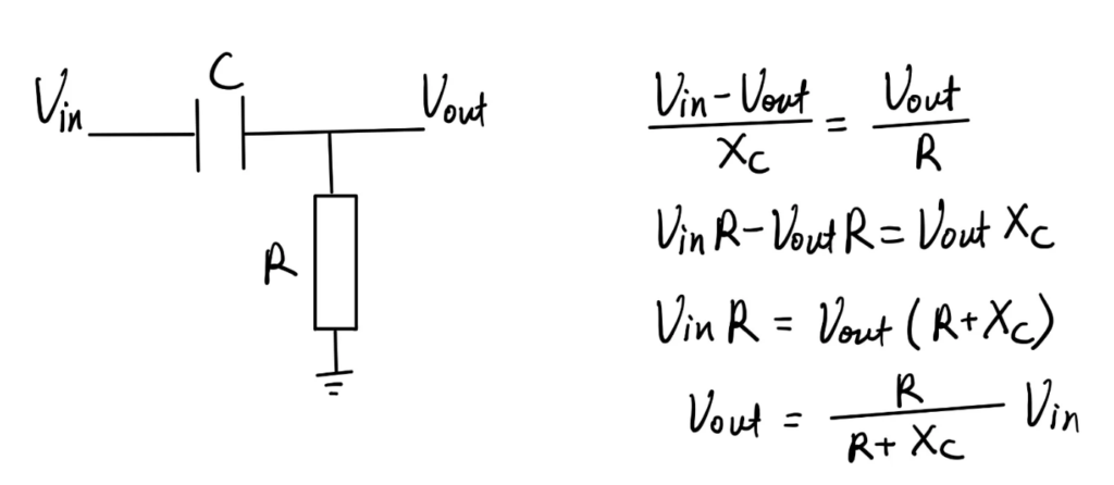
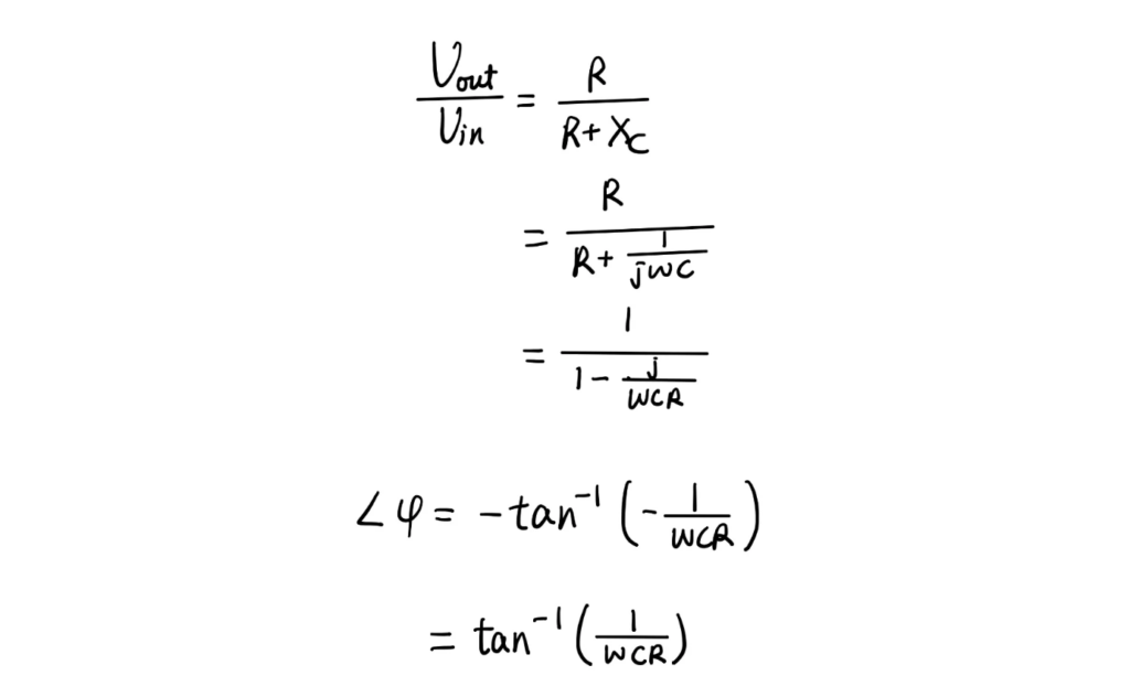
The circuit diagram below shows an first order RC high pass filter. By analysing the current flowing through the capacitor and resistor, we can establish an equation, potential difference across the capacitor divided by the capacitive reactance is equal to the potential difference across the resistor divided by the resistance R. After simplifying it, we will find the relationship between the input voltage and the output voltage.
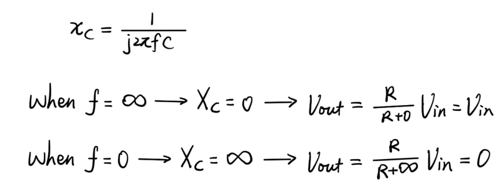
We can substitute critical values for frequency into the equation to find out whether this circuit is a high pass or low pass filter. If input frequency is infinity, the capacitive reactance is zero. It means that the capacitor can be seen as a wire, then the input voltage and output voltage are directly connected with each other and shares the same potential difference. On the other hand, when the input frequency is zero, the capacitive reactance goes to infinity. It means that the capacitor can be seen as an open circuit, therefore, the input voltage and output voltage are no longer connected to each other. So, the output voltage will be zero. From this trend, we can conclude that this circuit will only allow input that have high frequency to pass.
The frequency response of a actual RC high pass filter will look like the graph below. Unlike the ideal RC HPF, as long as the input frequency is below the cut-off frequency, the signal disappears immediately. At higher frequencies the actual filter provide minimum or zero attenuation and as the frequency decreases, the attenuation of the input signal will increase.
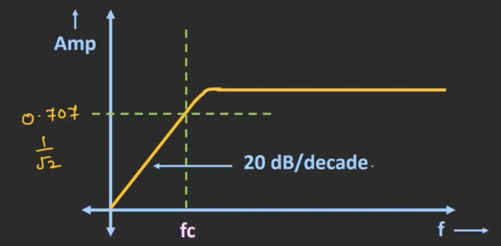
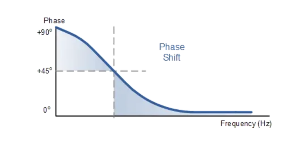
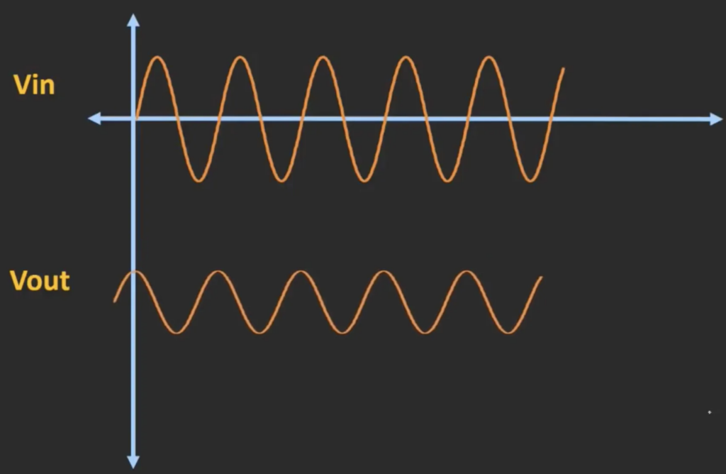
The RC high pass filter shares the same expression for cut-off frequency with the RC low pass filter. However the phase difference between the input and output signal is different from the RC LPF. As shown in the graph, the output voltage has a positive phase shift to the left.
The change of phase can be given by the following equation.
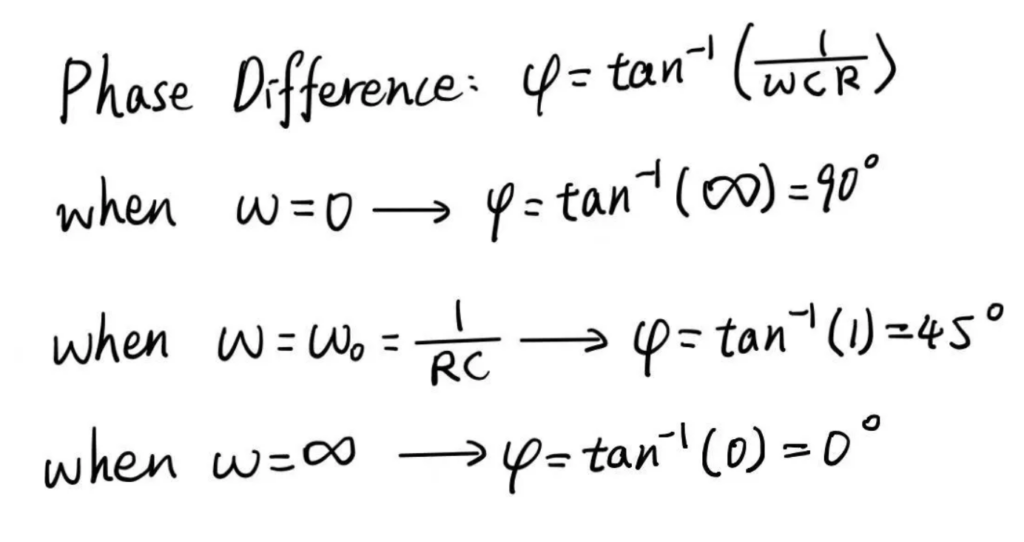
When the frequency is infinity, there would be no phase shift, the input signal can directly pass over the filter. When the frequency is the cut-off frequency, the phase difference is 45 degrees and when the frequency is zero, the phase difference is 90 degrees.
If we plot the phase difference versus frequency curve, it will look like the following.