Project Plan
After understanding the theoretical part of the PID control system, I decided to try to apply it in a real system. The main goal of this project is to achieve the control of the rotation angle of a gear motor with a user-controlled knob. The motor should rotate as much as the knob turns. In this project, the key points for judging success include whether the motor’s rotation will follow the knob in real time without delay and whether the motor will oscillate or be unstable.
Circuit-Based Design
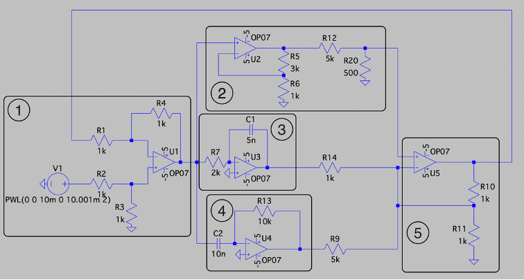
Based on my previous research, the whole PID circuit can be mainly divided into 5 different components as labeled in the diagram. Where:
- Component one is a differential amplifier for calculating the error value between the input signal and the feedback signal.
- Component two is the proportional control
- Component three is the integral control
- Component four is the differential control
- Component five is a summing amplifier circuit that adds up the output from the three controls. After understanding the theoretical part of the PID control system, I decided to try to apply it in a real system.
Motor Driver
One of the biggest problems that I have encountered during the project is driving the motor. The control system requires a motor drive circuit to work. This is because the maximum output current of an operational amplifier is only forty to fifty milliamperes, but at least five hundred milliamperes is required to drive a gear motor. Therefore, if there is no current amplifier circuit module in the circuit, the motor will not operate by just directly connecting the output of the PID control circuit to the input of the motor.
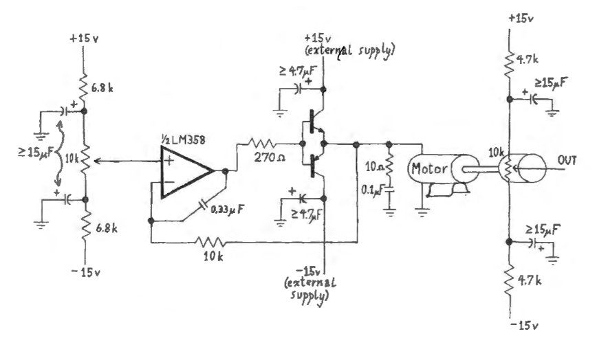
In the figure below, it shows a push-pull configuration amplifier, meaning that there are two transistors, one for “pushing” the current and the other for “pulling” the current. The NPN transistor is used to source current to the motor, and the PNP transistor is used to sink current from the motor. When the base voltage of the transistor is larger than 0.7 volts the current will flow from the external supply to the motor, and when the base voltage is smaller than negative 0.7 volts, the current will flow from the motor to the external supply. In this way, the motor can rotate both clockwise and anticlockwise.
Results
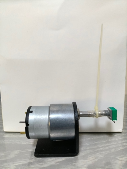
The figure below shows the gear motor that I used in my project. A positive voltage supply across its terminals with sufficient current will allow it to rotate clockwise, and a negative voltage supply will allow it to rotate anticlockwise. The motor below has an angular velocity of 107 rotations per minute and is connected with the shaft of the potentiometer using tape so that when the motor is rotating, the potentiometer is also rotating along with it. In this way, the position of the rotation of the motor can be tracked using the voltage across the potentiometer.
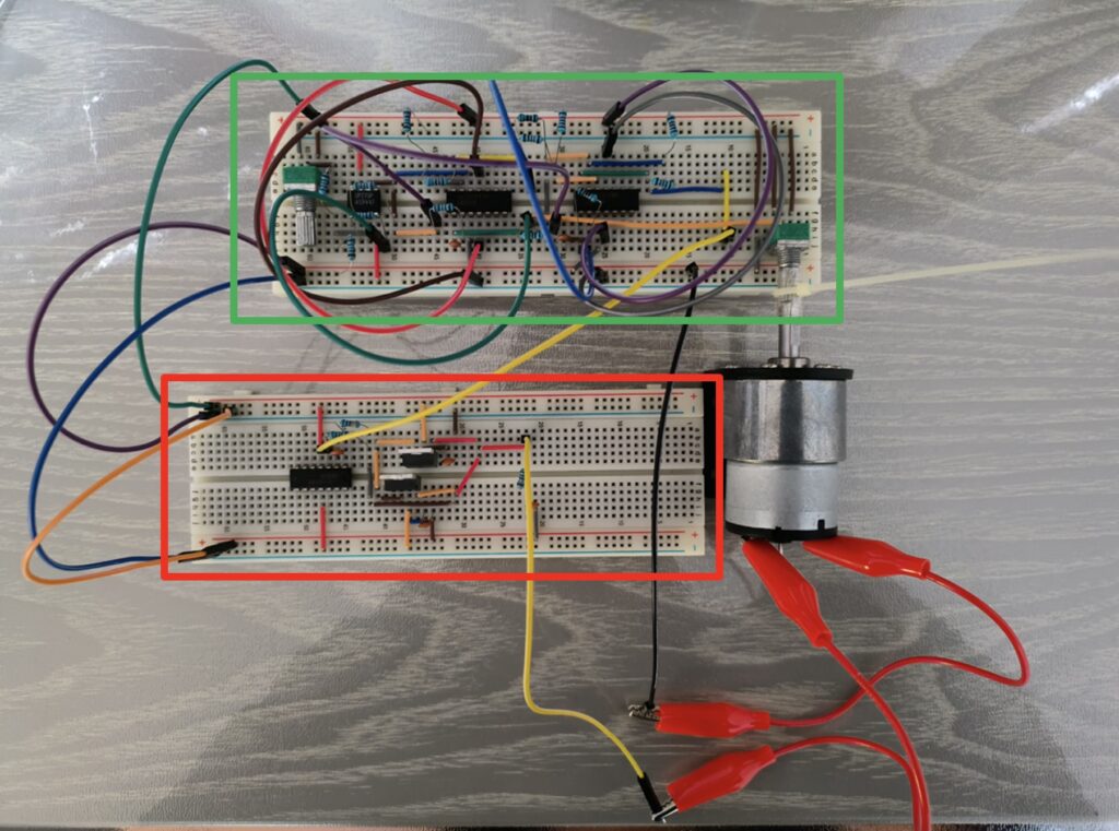
The final PID control circuit is shown in the figure below; it is built by directly transforming the designed circuit onto the breadboard. In the figure, the circuit on the top breadboard circled by the green box is the PID control circuit, and the circuit on the bottom breadboard circled by the red box is the current amplification circuit used to drive the motor.
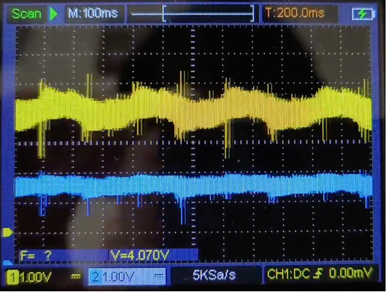
However, the predetermined PID coefficients did not provide a stable output signal to the system. The motor is oscillating with a small amplitude steadily and indefinitely around the set point as shown in the figure below, where the blue curve represents the input signal and the yellow curve represents the output signal from the motor armature. Both the output signals are full of random and stochastic ripples.
Reflection: Difficulties & Improvement
Bread Board Connection:
Many factors can influence the circuit built in the real world, causing it to have a different response compared to the simulated circuit. Some of the most important factors are as follows: firstly, the thin connection wire’s impedance is very large; secondly, the long connection wire will act as an antenna, which will receive electromagnetic interference; and finally, a magnetic field will be induced when multiple rings of wire are put together.
First of all, there are a lot of very thin wires on the breadboard that connect the different electronic components. The impedance of each of these wires cannot be ignored. These wires greatly affect the positive and negative supply voltages that feed the op amp, making them unstable. This is because the current in the circuit is constantly changing as the system makes corresponding adjustments to the input. When the voltage supply is connected to the circuit through a wire, there is a voltage drop, and most importantly, the voltage drop of the power supply also changes due to the changing current in the circuit; this is known as an unstable IR drop. It leads to the positive and negative voltage sources of the operational amplifier becoming not a stable value but an uncertain value that is randomly changing, causing the output voltage of the op amp to be unstable.
Secondly, this circuit will be subject to a lot of electromagnetic interference, also known as EMI, making the current and voltage in the circuit unstable. In the circuit, a long wire will have the characteristics of an antenna, which allows it to pick up electromagnetic interference in the air. These interferences are everywhere in the world; the main source of interference is electromagnetic waves, such as radio waves. These disturbances will cause the wire to induce unwanted voltage signals, thereby producing ripples in the feedback loops and disrupting the control. Moreover, there are a lot of long wires that connect different electrical components by going above the breadboard. These wires are in a ring structure; they act like some small solenoids. When there is a current flowing through the wires, these wires will induce a magnetic field; each magnetic field will interfere with each other. Since the current is changing continuously, the induced magnetic field is also changing, and these changes in the magnetic field
will cause an induced current in the wire, and these induced currents will also interfere with the
circuit.
The impact of these problems on the circuit can be achieved by designing the circuit on the PCB
board. First of all, compared with the thin and long wires on the breadboard, the welding traces on the PCB board will ensure that the wires in the circuit have only a small impedance, and the voltage drop of the wires will be reduced a lot. Secondly, the welding trace will greatly reduce the antenna characteristics of the wire and reduce the influence of electromagnetic interference on the circuit. The components are connected in such a way that there are no more loops of wires inducing magnetic fields, which reduces the inductive current pickup. In addition, installing a shielding on the PCB board can improve its performance. A good shielding is usually a layer of conductive metal covering, such as copper foil, over the circuit. This shielding acts as a Faraday cage to protect the circuitry inside, which can prevent any electric fields or electromagnetic waves from affecting anything within the cage.
Motor’s Response:
The final circuit built did not work as it had been simulated on the computer. Even though the simulation on the computer could allow the system to work properly, but I have not considered the effect of the motor’s property on the circuit’s behavior. This can cause some problems in the actual circuit because in the actual circuit output voltage is fed back through a gear motor instead of feeding the output voltage back to the input through a direct connection. The biggest difference between these two approaches is that when you add a mechanical system like a motor, it has its own complex dynamic behavior and inherent electrical and mechanical properties. For example, some of the mechanical properties that may influence the system include the back electromotive force, the motor’s friction, and its inertia.
First of all, motor’s rotation is caused by the interaction between the permanent magnetic field and the mechanical commutation. The back electromotive force is a voltage generated whenever the coil spins. It is generated because when the coil is cut through the magnetic field, a voltage that is opposing the input power will be induced. The magnitude of the back EMF is proportional to the speed of rotation of the motor, the faster the motor spins, the larger the back EMF will be. With the addition of it, the net voltage decreases, leading to the effective current driving the motor being less than the desired amount.
Secondly, in any mechanical system, there is friction and inertia. In the motor, there is a constant static friction force that must be overcome before the motor can begin to rotate. This will cause a delay in the system response because the motor will not respond to the control signal until the input voltage exceeds a certain threshold, which is a condition created in the system known as a dead zone. In addition, friction may also be different when the system is at rest, accelerating, or decelerating, which will make its response nonlinear, further complicating the mechanical system of the motor. Finally, the inertia of the motor rotation also causes a delayed response, because when there is an overshoot, the control signal will produce a driving force in the opposite direction of the current rotation, but due to inertia, the motor will not immediately start to rotate in the opposite direction but instead will first decelerate and then accelerate in the opposite direction.
A better approach to the problem that considers the effect of the motor on the system is by modeling the motor’s behavior using electrical circuits. Through the analysis of the working characteristics of the motor, it can be replaced by a series of circuits. In this way, when simulating on the computer, the model of the motor is added to the circuit so as to get a result that is more in line with the real situation, rather than an oversimplified result.